Design for bolt d1 nominal dia. Power is transmitted from driving shaft to flange on driving shaft through key from flange on driving shaft to the flange on driven shaft through bolts and then to the driven shaft through key again.

Machine Drawing Flange Coupling Design
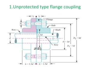
Calculating the diameter of the shaft Toque 1 Dimensions of the flange Couplings Outer diameter of hub D 2d Length of hub L 15d Pitch Circle Diameter of the bolts D1 3d Outer diameter of flange D2 4d Thickness of the Flange tf 05d Thickness of the protective Circumference Flange tp 05d.

. Flange coupling is a type of shaft coupling having two separate flanges which are mounted on the shaft end and both flanges are bolted together by means of nuts and bolts. These studies that by automating the design process to allow the customer more range of direct interactive control with the design companies could experience a significant reduction in. Design procedure for protected flange coupling 1.
Standard shaft sizes can be selected from Table 35a Page 57 Find the dimensions of flanges by empirical relations on Pg 251 and Pg 252 The inner and outer diameters of the hub are D and D 1. Analytical Design of Flange Coupling Design draw a cast iron flange coupling for a mild steel shaft transmitting 90 Kw at 250 rpm. Home Tags Flange coupling design procedure.
Types of flat belt drives hydraulic braking system pdf flange coupling drawing pdf coefficient of friction table industrial safety measures wikipedia characteristics. Check the bolt for safety. Cross-sectional area and Material therefore minimize weight by maximizing Yield Stress Densitym F L DensityYield Stress Eliminate free variable.
𝜏 𝑇 𝜋 1 4 4 u t N 1 t. Design for hub Step 3. Taking into consideration the service factor of 15 the design torque is given by Td 60 106 kW 2πn 15 60 106 375 15 2π 180 298415518 N mm 16Td πd 3 or 76 16 298415518 πd 3 Diameter of shaft d 5848 or 60 mm.
4 For the 1st procedure the coupling is designed as a solution of the given case which determines the dimensions for the main coupling parts. Design Automation of Flange Coupling using NX 100. 1 Select suitable material for the shaft and design the shaft.
This video explains Design Procedure for Unprotected type flange Coupling in simple way. The flanges are connected together by means of bolts arranged on a circle concentric to shaft. To reduce the transmission of shock loads from one shaft to another.
Design of shaft Step 4. Steps of design Rigid flange coupling Step1 Calculate the diameter torque to be transmitted Mt- use the equation. M ALDensity FA Yield Stress Design of flange coupling procedure.
Explain the design procedure of bush pin type flexible coupling with neat sketch Answer. Flange coupling consists of two flanges keyed to the shafts. -Improve Existing Turbine Flange Connection for Ease of Assembly -Reduce Width of Guard Pilot -Reduce Amount of Interference at Pilot -Improve Overall Flange Connection Design -Use Standard Design Bolting -Improve Procedure -Leave Coupling Adapter in Place.
Design specification of coupling. Design for flange Step 5. Shaft couplings are used in machinery for several purposes.
To provide for connection of shaft of units those are manufactured separately. Design of Flange Coupling. Couplings are elements used to.
Flange coupling design procedure. To provide for misalignment of the shaft or to introduce mechanical flexibility. Design for bolts Step 2.
The shaft diameter d. A spigot A on one flange and a recess on the opposing face is provided for ease of assembly. Step 2 Calculate the diameter of the shaft-d-use the equation Assume di0 Round off the shaft diameter to R20 series.
It consist of two shafts two key flanges key pin rubber bush brass bush pin following are the designations of various coupling dimensions which are use for the design procedure. The design procedure is generally based on determining the shaft diameter d for a given torque transmission and then following empirical relations different dimensions of the coupling are obtained. Types of Flange Coupling Unprotected type In this type of coupling each shaft is keyed to the boss of a flange with counter sunk key and both flanges are coupled together with rings of bolts.
3 Select no of bolts select bolt material design PCD. Re placing the. Design of flan ge coupling includes the design of hubs flanges key and bolts 4The strength o f the members in flange coupling are should be go od enough for app lied load7.
A protective type rigid flanged coupling required to transmit 25 KW at 100 rpm. This paper deals with developing a program code for the protected type flange coupling in an Object Oriented Programming OOP language like PYTHON which takes input from designers and accordingly calculates the specifications of the coupling using design standard formulas and iterative procedures until the design meets the safe criteria. Design for key We have also used.
Check for different failure modes can then be carried out. 2 select suitable material for the key select cross section of the key. Rigid Flange Coupling Department of Mechanical Engineering 17 Obtain the shaft diameter.
For bolts and bolt size.
Anuniverse 22 Notes Md I Coupling 6 Design Of Flange Coupling Youtube

Explain The Design Procedure Of Bush Pin Type Flexible Coupling With Neat Sketch Mechanical Engg Diploma Simple Notes Solved Papers And Videos

Problem On Flange Coupling Youtube

Design Procedure For Flange Coupling Youtube

Flange Coupling Flange Coupling Design Types Of Flange Coupling

Design Of Flange Coupling Engineers Gallery

Flange Coupling Flange Coupling Design Types Of Flange Coupling
Design Of Flange Coupling Engineers Gallery
0 comments
Post a Comment